Archive

Yearly Archives: 2013

Update: I’ve revisited this comparison for QGIS 3 in Revisiting point & polygon joins

Joining polygon attributes to points is a pretty common geoprocessing step. There are multiple ways to solve the problem in QGIS, so I thought I’d have a look at how they perform. There is Join attributes by location in the Vector menu and Add polygon attributes to points in the Processing toolbox.

My test data: Two shapefiles with 18,713 points and 17,397 irregular polygons.

(Some system specs: 1.3GHz dualcore with 4GB RAM)

And here are the results:

SAGA Add polygon attributes to points: 44 seconds
Vector | Data management tools | Join attributes by location: killed after 16 hours

This point clearly goes to Processing and the SAGA algorithm it provides access to. Join attributes by location offers some nice options for aggregating data but it just can’t cope with the number of features in this test.

To measure execution time (in a very unscientific way), I just ran the tool from the python console using:

import datetime
import processing
print datetime.datetime.now()
processing.runalg("saga:addpolygonattributestopoints","C:/Users/Anita/poi_wien.shp","C:/Users/Anita/REALNUT2009OGD.shp","NUTZUNG_CO",None)
print datetime.datetime.now()

Some notes of caution:
SAGA comes readily installed in OSGeo4W. As far as I know, the stand-alone installer for Windows currently does not include SAGA but it can be installed manually. On Ubuntu, the standard repos only contain SAGA 2.0.8 but 2.1 is required.

Great shot! – photo by Kenneth Field

FOSS4G 2013 in Nottingham is history. It was my first FOSS4G and a great event. Meeting so many people for the first time in person is really exciting. I had the great chance to present some of the work I did at AIT on comparing street networks. If you couldn’t make it to the conference or missed my talk, here’s the chance to hear it again:


(Tip: You’ll find many more FOSS4G presentations on Youtube.)

Slides and the paper are listed on my publications page. If you are interested in the code, you can find it on Github.

So far, I couldn’t find Tim Sutton’s QGIS keynote video on Youtube. Maybe it will be uploaded later. In the meantime, you can enjoy his slides.

Of course, you already know that the release of QGIS 2.0 was also announced at FOSS4G. In case you haven’t seen the great list of new features yet, have a look at the visual changelog.

Map Gallery – photo by Kenneth Field

The results of the FOSS4G 2013 map contest have also been published now. Thanks to everyone who voted for my entry “FLEET Taxi Tracking” which made it to Runner-up: Best Anti-map Map!

Yesterday, I received an interesting QGIS question:

is there a way to make road label font size depending on road lenght (with osm layer)?
Indeed, it could be interresting to see all roads, even the smallest, on a city map rendering.

Thanks to the data-defined labeling capabilities of the new QGIS version, we can!

Just click the slightly weird symbol right of the label text size and select Edit …

Since OSM data is in WGS84 by default, street length will be measured in degrees and therefore the values will be small. To get to a reasonable font size, I selected $length * 1000.

The second part of the question can be addressed using a setting in the Rendering section which is – very descriptively – called “Show all labels for this layer (including colliding labels)”.

labelexperiment

While I doubt that this simple method alone will create a great road map, I think it’s still an interesting exercise with sometimes surprising results.

It’s almost here, the biggest open source GIS event of the year: the FOSS4G 2013 in Nottingham. It’s going to be my first visit to FOSS4G and I’m looking forward to present a project I did together with two colleagues at AIT where we compared OpenStreetMap to the official Austrian street network using tools developed in QGIS 1.8 Sextante. The presentation is scheduled for the first day and it would be great to meet you there:

I also have the honor to present Victor Olaya’s Sextante/Processing in a workshop together with Paolo Cavallini on the 20th:

I guess I owe Victor a geobeer or two ;-)

See you in Nottingham! And for those who can’t make it to the UK: I’ll try to keep you posted if the conference wifi allows it.

This post describes the three simple steps necessary to create a vintage-looking map using the blending feature in QGIS 2.0’s print composer. This is what we are aiming for:

alaska_oldpaper

1. Prepare the map

Like any other map, this one starts in the QGIS main window. Try to stick with earthy colors which will go well with the old paper look. For labels, try fonts which look like handwriting.

alaska_oldschool_overview

Once you are happy with your map

2. Prepare the composition background

To get that vintage feel, we need a background image with a great texture. You can find such textures on sites like lostandtaken.com. Download one you like and add it to an empty print composer. Make sure it covers the whole paper:

alaska_oldschool_bg

Lock the image by right-clicking it once – a small lock icon should appear in the upper left corner.

3. Finish the composition

The final step is to add the map on top of the background image. To make our nice background texture shine through, we enable the “multiply” blending mode in the map’s rendering options:

alaska_oldschool_print

Feel free to add north arrows or drawings of dragons as finishing touches.

This post covers a simple approach to calculating isochrones in a public transport network using pgRouting and QGIS.

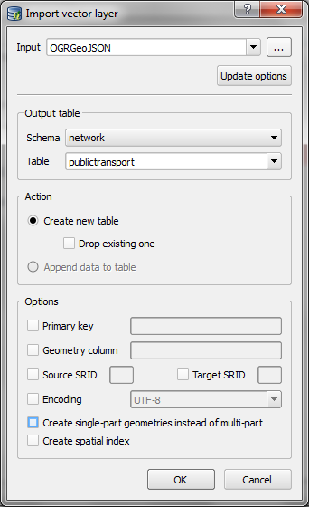
For this example, I’m using the public transport network of Vienna which is loaded into a pgRouting-enable database as network.publictransport. To create the routable network run:

select pgr_createTopology('network.publictransport', 0.0005, 'geom', 'id');

Note that the tolerance parameter 0.0005 (units are degrees) controls how far link start and end points can be apart and still be considered as the same topological network node.

To create a view with the network nodes run:

create or replace view network.publictransport_nodes as
select id, st_centroid(st_collect(pt)) as geom
from (
	(select source as id, st_startpoint(geom) as pt
	from network.publictransport
	) 
union
	(select target as id, st_endpoint(geom) as pt
	from network.publictransport
	) 
) as foo
group by id;

To calculate isochrones, we need a cost attribute for our network links. To calculate travel times for each link, I used speed averages: 15 km/h for buses and trams and 32km/h for metro lines (similar to data published by the city of Vienna).

alter table network.publictransport add column length_m integer;
update network.publictransport set length_m = st_length(st_transform(geom,31287));

alter table network.publictransport add column traveltime_min double precision;
update network.publictransport set traveltime_min = length_m  / 15000.0 * 60; -- average is 15 km/h
update network.publictransport set traveltime_min = length_m  / 32000.0 * 60 where "LTYP" = '4'; -- average metro is 32 km/h

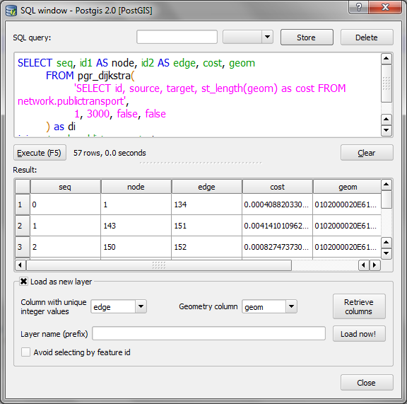
That’s all the preparations we need. Next, we can already calculate our isochrone data using pgr_drivingdistance, e.g. for network node #1:

create or replace view network.temp as
 SELECT seq, id1 AS node, id2 AS edge, cost, geom
  FROM pgr_drivingdistance(
    'SELECT id, source, target, traveltime_min as cost FROM network.publictransport',
    1, 100000, false, false
  ) as di
  JOIN network.publictransport_nodes pt
  ON di.id1 = pt.id;

The resulting view contains all network nodes which are reachable within 100,000 cost units (which are minutes in our case).

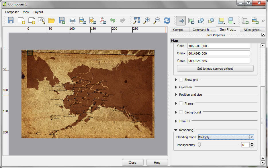
Let’s load the view into QGIS to visualize the isochrones:

isochrone_publictransport_1

The trick is to use data-defined size to calculate the different walking circles around the public transport stops. For example, we can set up 10 minute isochrones which take into account how much time was used to travel by pubic transport and show how far we can get by walking in the time that is left:

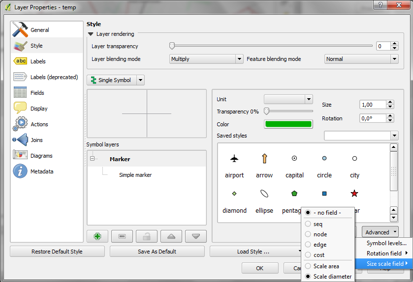
1. We want to scale the circle radius to reflect the remaining time left to walk. Therefore, enable Scale diameter in Advanced | Size scale field:

scale_diameter

2. In the Simple marker properties change size units to Map units.
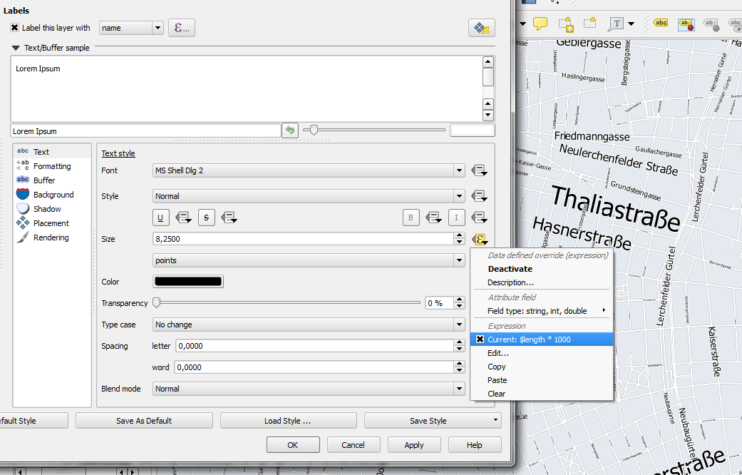
3. Go to data defined properties to set up the dynamic circle size.

datadefined_size

The expression makes sure that only nodes reachable within 10 minutes are displayed. Then it calculates the remaining time (10-"cost") and assumes that we can walk 100 meters per minute which is left. It additionally multiplies by 2 since we are scaling the diameter instead of the radius.

To calculate isochrones for different start nodes, we simply update the definition of the view network.temp.

While this approach certainly has it’s limitations, it’s a good place to start learning how to create isochrones. A better solution should take into account that it takes time to change between different lines. While preparing the network, more care should to be taken to ensure that possible exchange nodes are modeled correctly. Some network links might only be usable in one direction. Not to mention that there are time tables which could be accounted for ;)

This post is a quick instruction for installing Postgres 9.2, PostGIS 2.0 and pgRouting 2.0.

  1. For Postgres, download the installer from enterprisedb.com.
  2. Run the installer. You’ll have to pick a superuser password – remember it, you’ll need it again soon.
  3. At the end of the installation process, allow the installer to start Stack Builder.
  4. In Stack Builder, select the Postgres 9.2 installation and install PostGIS from the list of available extensions.
  5. The PostGIS installation procedure will prompt you for the superuser password you picked before.
  6. I suggest letting the installer create a sample database We’ll need it later anyway.

Now for the pgRouting part:

  1. Download the pgRouting zip file for your system (32 or 64 bit) from Winnie.
  2. Unzip the file. It contains bin, lib and share folders as well as two text files.
  3. Copy these folders and files over to your Postgres installation. In my case C:\Program Files\PostgreSQL\9.2

Installation – done.

Next, fire up pgAdmin. If you allowed the PostGIS installer to create a sample database, you will find it named postgis20 or similar. Otherwise just create a new database using the PostGIS template database. You can enable pgRouting in a database using the following steps:

  1. In postgis20, execute the following query to create the pgrouting extension. This will add the pgRouting-specific functions:
    CREATE EXTENSION pgrouting;
  2. Test if everything worked fine:
    SELECT pgr_version();

    It should return "(2.0.0-dev,v2.0.0-beta,18,a3be38b,develop,1.46.1)" or similar – depending on the version you downloaded.

pgadmin_pgrouting

How about some test data? I’ll be using the public transport network of the city of Vienna provided in GeoJSON format from http://data.wien.gv.at/daten/geo?service=WFS&request=GetFeature&version=1.1.0&typeName=ogdwien:OEFFLINIENOGD&srsName=EPSG:4326&outputFormat=json:

    1. Just copy paste the url in Add Vector Layer | Protocol to load the dataset.
    2. Use DB Manager to load the layer into your database. (As you can see in the screenshot, I created a schema called network but that’s optional.)

import_publictransport

  1. To make the line vector table routable, we use pgr_createTopology. This function assumes the columsn called “source” and “target” exist so we have to create those as well:
    alter table network.publictransport add column source integer;
    alter table network.publictransport add column target integer;
    select pgr_createTopology('network.publictransport', 0.0001, 'geom', 'id');
    

    I’m quite generously using a tolerance of 0.0001 degrees to build the topology. Depending on your dataset, you might want to be more strict here.

  2. Let’s test it! Route from source #1 to target #3000 using pgr_dijkstra:
    SELECT seq, id1 AS node, id2 AS edge, cost, geom
      FROM pgr_dijkstra(
        'SELECT id, source, target, st_length(geom) as cost FROM network.publictransport',
        1, 3000, false, false
      ) as di
      JOIN network.publictransport pt
      ON di.id2 = pt.id ;

    Note how the query joins the routing results and the network table together. (I’m aware that using the link length as a cost attribute will not lead to realistic results in a public transport network but bear with me for this example.)

  3. We can immediately see the routing results using the Load as new layer option:

select_dijkstra
route

Nice work! pgRouting 2.0 has come a long way. In a post from April this year, Boston GIS even announced to add pgRouting into the Stack Builder. That’s going to make the installation even more smooth.

As mentioned in my previous post, all plugins need an update to function in QGIS master – soon to be 2.0. The OpenLayers plugin is one of the most popular plugins but so far has not been updated by the developer. If you miss it, you can get a fixed version from qgis.nl Temporary Fix for OpenLayers Plugin thanks to Richard!

openlayers

As I’m sure you have already heard, QGIS 2.0 will come with a new Python API including many improvements and a generally more pythonic way of doing things. But of course that comes with a price: Old plugins (pre 2.0) won’t work anymore unless they are updated to the new version. Therefore all plugin developers are encouraged to take the time and update their plugins. An overview of changes and howto for updates is available on the QGIS wiki.

TimeManager for QGIS 2.0 will be available from day 1 of the new release. I’ve tested the usual work flows but don’t hesitate to let me know if you find any problems. The whole update process took two to three hours … sooo many signals to update … but all in all, it was far less painful than expected, thanks to everyone who contributed to the wiki update instructions!

In QGIS 2.0, the old “size scale” field has been replaced by data-defined properties which enable us to control many more properties than jut size and rotation. One of the often requested features – for example – is the possibility for data-defined colors:

datadefinedproperties

Today’s example map visualizes a dataset of known meteorite landings published on http://visualizing.org/datasets/meteorite-landings. I didn’t clean the data, so there is quite a bunch of meteorites at 0/0.

To create the map, I used QGIS 2.0 feature blending mode “multiply” as well as data-defined size based on meteorite mass:

meteorites1

Background oceans and graticule by NaturalEarthData.